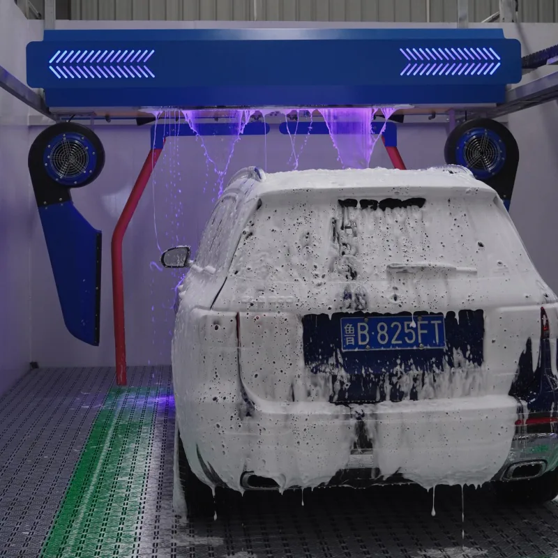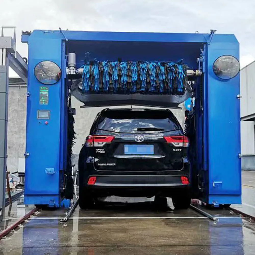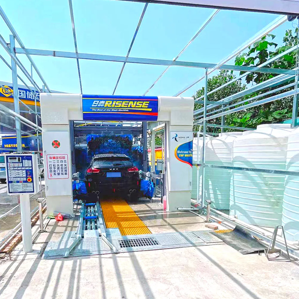
An automatic car wash needs more space than the equipment footprint. A complete layout must accommodate the compatible vehicle envelope, machine travel, safety and maintenance clearances, approach and exit, queueing, an equipment or utility area, drainage and wastewater management. There is no single universal bay dimension: the approved space depends on the wash architecture, model, vehicle mix and local building conditions.
This guide shows buyers how to measure a candidate site before selecting equipment. Final construction dimensions must always follow the supplier’s approved layout and foundation drawings.
Do not ask only, “Will the machine fit?” Ask whether vehicles, people, utilities and maintenance work can move safely around the complete system.
The six space zones in an automatic car wash project
| Zone | What it must accommodate | Common planning error |
|---|---|---|
| Approach | Turning, alignment, vehicle identification and driver guidance | Measuring only the doorway |
| Queue | Peak waiting vehicles without blocking roads, fuel pumps or parking | Using the public road as overflow space |
| Wash bay | Vehicle envelope, equipment, travel path and spray containment | Using equipment size as the required room size |
| Maintenance clearance | Inspection, component removal, safe access and cleaning | Placing walls or columns too close to the machine |
| Equipment and utilities | Pumps, controls, chemicals, tanks, air and water treatment | Leaving no protected service area |
| Exit and finishing | Safe departure, inspection, optional detailing and traffic merge | Crossing the incoming queue |
Begin with the largest compatible vehicle
Record the maximum length, body width and height of the vehicles the site intends to wash. Add mirrors, roof racks, antennas, light bars, rear steps, spare wheels and other projections. A building can appear large enough while a vehicle accessory remains outside the machine’s approved sensing or movement envelope.
Separate the building’s physical opening from the system’s approved vehicle limit. The machine may require more space around the vehicle for sensors, wash arms, brushes, dryers or conveyor components. Buses and heavy trucks generally need purpose-built equipment rather than a passenger-car bay made slightly larger.
Measure the wash bay as a working volume
Measure clear internal length, width and height—not nominal building dimensions. Mark columns, beams, pipes, lights, doors, cable trays, ventilation ducts, wall projections and floor obstructions. Record the lowest overhead point and the narrowest usable width along the complete machine and vehicle path.
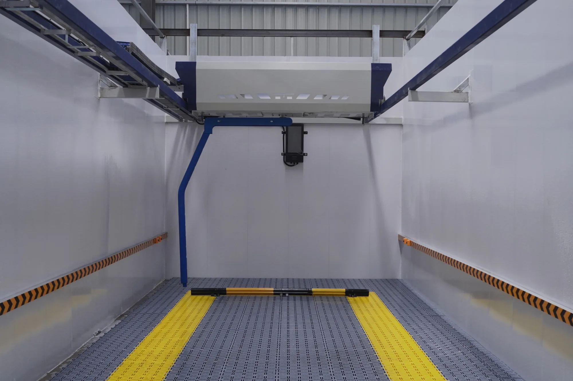
- Clear length: include machine travel, vehicle positioning, stops and access at both ends.
- Clear width: include vehicle width, machine structure, spray containment and maintenance access.
- Clear height: check the machine’s highest component, vehicle accessories, doors, beams and services.
- Floor level: record slopes, pits, trenches, rails, embedded pipes and existing foundations.
- Door opening: verify that the opening, tracks and raised door do not enter the required envelope.
How wash architecture changes the space requirement
Touchless and rollover in-bay systems
The vehicle normally remains stationary while the gantry or wash assembly moves. The bay must contain the machine’s travel and provide room for vehicle positioning, wheel stops or guidance, spray control and servicing. A compact equipment footprint does not remove the need for an approach, queue or protected equipment area.
Conveyor tunnel systems
A tunnel needs a continuous vehicle path through loading, conveyor travel, wash modules, drying and exit. Site length, queue design and safe merge space become central decisions. The project also needs room for conveyor service, chemical and pump equipment, and staff movement along the line.
Heavy-vehicle systems
Bus and truck projects must be planned around larger dimensions, turning paths, axle loads, mirrors, roof equipment, contamination and possible chassis cleaning. They require a separate engineering review and should not use passenger-car dimensions as a starting specification.
Plan the approach, queue and exit
A technically adequate wash bay can still fail operationally if vehicles cannot approach in a straight, controlled path. Draw the largest vehicle turning into the site, joining the queue, aligning with the bay and leaving without reversing into traffic. Consider driver visibility, signs, height barriers, wheel guides and the location of payment or access-control equipment.
Queue capacity should be based on peak arrivals rather than an average day. Prevent waiting vehicles from blocking public roads, fuel pumps, workshop doors, parking circulation or pedestrian routes. At the exit, allow room for inspection or optional manual finishing without stopping the wash cycle.
Reserve an equipment and utility area
The operating system may require pumps, tanks, chemical dosing, an electrical cabinet, compressed air, water treatment and spare-parts storage. These components need a dry, ventilated, accessible and appropriately protected location. Chemical storage and electrical equipment should not be placed wherever unused floor area remains after construction.
- service access around pumps, filters and controls;
- safe chemical delivery and container replacement;
- ventilation, drainage and climate protection;
- short, serviceable pipe and cable routes;
- space for water treatment, recycling or future options;
- clear separation where required by local rules and equipment instructions.
Coordinate floor, drainage and foundations early
Floor design affects the usable height, machine alignment, water movement and maintenance. Show existing concrete thickness and condition, floor levels, slopes, channels, pits and wastewater route. Do not place drains or trenches based only on a concept image; coordinate them with the approved foundation and utility drawing.
Removable open-grid flooring may improve surface drainage and access in some layouts, but it does not replace correct floor slopes, structural capacity, sediment management or wastewater treatment. Review the water recycling guide if reuse is part of the project.
Prepare a useful site survey
A supplier can evaluate space more reliably when the buyer provides a dimensioned plan and current photographs. Include a scale or reference dimension in photos and identify where the images were taken. For an existing building, record every fixed obstruction rather than sending only a wide view of the empty floor.
- site plan with north direction and property boundaries;
- building plan and section with clear dimensions;
- entrance, exit, road width and turning restrictions;
- columns, beams, doors, windows and wall projections;
- floor levels, slopes, drains and existing pits;
- water, power, air and wastewater connection points;
- equipment-room options and maintenance access;
- vehicle photographs and maximum dimensions;
- photos and video of the full approach-to-exit route.
Common space-planning mistakes
- Ordering from the machine footprint before receiving an approved layout;
- using building width instead of clear usable width;
- forgetting raised doors, beams, pipes or lights;
- leaving no clearance for maintenance or component removal;
- designing the bay without the approach and queue;
- placing the equipment room too far away or in a wet, inaccessible area;
- completing drains and foundations before model confirmation;
- assuming every passenger, van, bus or truck can use one bay.
Confirm dimensions before construction
Use published dimensions only for early screening. Before civil work, obtain the model-specific general arrangement, foundation, rail or anchoring, drainage and utility drawings. Freeze the configuration, verify it against the vehicle register and site survey, and record drawing revisions.
Explore the YOLO automatic car wash range, use the installation checklist, or review solutions by operating scenario before requesting a model-specific layout.